Xray Inspection Machine
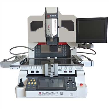
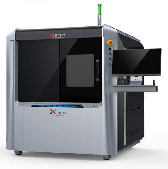
The Dinghua X-Ray Non-Destructive Testing Instrument DH-X8 features a closed X-ray tube, a high-definition digital flat panel detector, laser automatic navigation and positioning, and CNC detection mode with X/Y/Z axis motion control. It also includes a 360-degree rotation function for multi-angle inspection, offering simple and fast operation to quickly locate target defects.
Description
What Is an X-Ray Inspection Machine?
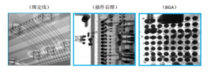
X-Ray Inspection Machine is a non-destructive testing (NDT) system designed to inspect hidden structures and solder joints inside electronic assemblies without damaging the product. Using high-resolution X-ray imaging technology, the system can detect defects such as solder voids, bridging, cold joints, insufficient solder, and component misalignment that cannot be identified through visual inspection.
Products Advantages
1. The X-ray source adopts a closed X-ray tube, featuring long lifespan, maintenance-free operation, and 130KV voltage.
2. The new-generation high-definition digital flat-panel X-ray inspection detector, with a high-resolution design, delivers optimal images in an extremely short time.
3. Laser automatic navigation and positioning enable quick selection of the shooting position.
4.X/Y/Z axis motion control for easy operation.
5. CNC inspection mode for fast automatic detection of multi-point arrays.
6. Tiltable angle: ±60°; multi-angle tilt inspection makes it easier to detect sample defects.
7. Optional 360° rotation function. X-ray machine for pcb
8. Visualised high-definition navigation window for convenient operation and quick location of the inspection target.
9. The industrial X-ray inspection system has a 550 mm* 550 mm loading stage.
10. Simple and fast operation allows quick identification of target defects; users can get started after 2 hours of training.
Detectable Defects
The X-Ray Inspection Machine can identify a wide range of hidden manufacturing defects, including:
- BGA voids
- BGA bridging
- Cold solder joints
- Insufficient solder
- Excess solder
- Through-hole solder defects
- Open circuits
- Short circuits
- Cracked solder joints
- Component misalignment
- Internal PCB structural defects
Products Specifications
| X-ray Source |
Type: Closed reflective target microfocus Voltage: 40-130KV (configurable) Current: 10-300uA Max Power: 39W Microfocus Size: 5μm |
| Flat-Panel Detector |
Type: Amorphous silicon flat-panel Pixel Matrix: 1536×1536 Field of View: 130.56×130.56mm Spatial Resolution: ≥5.5Lp/mm Pixel Pitch: 85μm |
| Loading Stage |
Size: 550×550mm Inspection Range: 500×500mm Max Load: 10kg Radiation Isolation: 5mm thickened lead plate |
| Chassis & Electrical |
Dimensions: 1450(L)×1530(W)×2000(H)mm Weight: ~1500kg Power Supply: AC220±10% 10A Total Power: 1500W |
| Safety & Environment |
Operating Env: 22±3℃, 50%RH±10%RH Radiation Safety: ≤1μSV/H (meets international standards) Key Protections: Interlock, electromagnetic window lock, emergency stop |
| Dimensions | 1450mm(L) × 1530mm(W) × 2000mm(H) |
| Weight | Approx. 1500kg |
| Power Supply | AC220±10% 10A |
| Total Power | 1500W |
| Temp & Humidity | 22±3℃, 50%RH±10%RH |
| Radiation Protection | Steel-lead-steel structure; leaded glass windowDose rate ≤1μSV/H (meets international standards) |
| Key Protections | 1. Safety interlock (door open → X-ray disabled)2. Electromagnetic window lock (X-ray on → window locked)3. Emergency stop button (one-press power cut) |
| Manufacturer | Shenzhen Dinghua Innovation Automation Co., Ltd.(X-RAY / BGA rework station specialist) |
| Safety Interlock | 3 high-sensitivity limit switches are installed at the front and rear door positions. When the door is opened, the X-ray source is automatically protected and the X-ray tube cannot be activated. |
| Electromagnetic Safety Door | The observation window is equipped with an electromagnetic switch. When the X-ray tube is in operation, the observation window cannot be opened. |
| Emergency Stop Button | In case of emergency, press to cut off power immediately. |
Software functions
| Function Module | Description |
|---|---|
| Operation Method | All operations are completed via joystick + keyboard + mouse (the motion axis can be moved by dragging the mouse; the X-ray tube Z-axis can be zoomed in/out via pulley sliding). |
| X-ray Tube Control | Click the button with the mouse to turn the X-ray on/off; the tube voltage and tube current values are displayed in real time. Adjustments can be made via up/down buttons, slider dragging, or manual input; the tube power and microfocus size are also displayed in real time. |
| Status Bar | Indicates interlock status, preheating status, and X-ray on/off status through red/green flashing lights. |
| Category | Item | Description |
|---|---|---|
| (General Functions) | Image Effect Adjustment | Freely adjust the image's filter level, brightness, contrast, and filter to achieve the desired image effect. |
| Navigation Window | After the high-definition color camera captures the platform image, click any position on the photo to quickly locate the inspection target. | |
| Motion Axis Status | Displays real-time coordinates and magnification rate. | |
| Inspection Results | Sequentially displays each measurement result (void rate, distance, area, and other measurement items). | |
| Speed Control | Adjust the axis movement speed (slow, normal, fast) via the space bar and software. | |
| Void Rate Measurement | Automatic Calculation | Measure voids in packaged components (e.g., BGA, QFN); automatically calculate the BGA void proportion in the selected area. Set thresholds to automatically determine void rate and maximum void rate. |
| Parameter Adjustment | Adjust thresholds, size, Blob type, and calculation parameters to get accurate automatic calculation results. | |
| Dimension Calculation | Through-Hole Solder Ratio Calculation | Mainly used to measure the wetting rate of through-hole components; obtain the proportion and height of the component's soldering surface via rectangular selection. |
| Quick Distance Measurement | Get the distance between two points via arbitrary frame selection. | |
| Point-Line Distance | Get the distance between a point and a line via arbitrary point and line selection. | |
| Angle | Set points A and B as the baseline, then click point C to measure the included angle between rays BA and BC. | |
| Circle | Mainly used to measure circular components (e.g., solder balls); select any circular component via frame selection to get its circumference, area, and radius. | |
| Horizontal Rectangle | Mainly used to measure square components; select a square via frame selection to get its length, width, and area. |
| Automatic Inspection | Item | Description |
|---|---|---|
| CNC Inspection | For multiple inspection points, simply set any position and measurement items; the software will automatically capture each inspection point and save the images. | |
| Laser Positioning | Red dot laser positioning device, dual assistance for easy navigation. |
Example images
fAQ