Reflow Touch Screen BGA Rework Machine
1. Automatic soldering,de-soldering and mounting BGA IC chip
2. Optical CCD camera lens:90°open/folding, HD 1080P
3. Camera magnification: 1x - 220x
4. Placement accuracy: ±0.01mm
Description
1.Specification of Reflow Touch Screen BGA Rework Machine
| Power | 5300W |
| Top heater | Hot air 1200W |
| Bottom heater | Hot air 1200W.Infrared 2700W |
| Power supply | AC220V±10% 50/60Hz |
| Dimension | L530*W670*H790mm |
| Positioning | V-groove PCB support, and with external universal fixture |
| Temperature control | K type thermocouple, closed loop control, independent heating |
| Temperature accuracy | ±2°C |
| PCB size | Max 450*490 mm.Min 22*22 mm |
| Workbench fine-tuning | ±15mm forward/backward,±15mm right/left |
| BGA chip | 80*80-1*1mm |
| Minimum chip spacing | 0.15mm |
| Temp Sensor | 1(optional) |
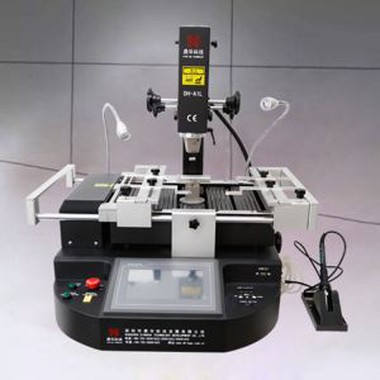
2.Details of Reflow Touch Screen BGA Rework Machine
CCD camera( precise optical alignment system) ;
HD digital display ;
Micrometer (adjust angle of chip) ;
Hot air heating;
HD touch screen interface , PLC control ;
Led headlamp ;
Joystick control .


3.Why Choose Our Reflow Touch Screen BGA Rework Machine?


4.Certificate of Reflow Touch Screen BGA Rework Machine

5.Packing & Shipment


Related Knowledge
BGA Chip Rework Operation Process Guidelines
I. BGA Chip Repair Process Guidelines
This article primarily describes the de-soldering and ball-planting operation procedures for BGA ICs, and the precautions to take when working with leaded and lead-free boards on the BGA rework station.
II. BGA Chip Repair Process Description
The following issues should be kept in mind during BGA maintenance:
- To prevent over-temperature damage during the de-soldering process, the hot-air gun temperature should be pre-adjusted before use. The required temperature range is 280–320°C. The temperature should not be adjusted during the de-soldering process.
- Prevent static electricity damage by wearing an electrostatic wrist strap before handling components.
- To avoid damage from the hot-air gun's wind and pressure, adjust the hot-air gun's pressure and airflow before use. Avoid moving the gun while performing de-soldering.
- To prevent damage to the BGA pads on the PCBA, gently touch the BGA with tweezers to check whether the solder has melted. If the solder can be removed, ensure the unmelted solder is heated until it melts. Note: Handle carefully and do not use excessive force.
- Pay attention to the positioning and orientation of the BGA on the PCBA to avoid secondary solder ball formation.
III. Basic Equipment and Tools Used in BGA Maintenance
The following are the basic equipment and tools required:
- Intelligent hot-air gun (used for removing the BGA).
- Anti-static maintenance desk and electrostatic wrist strap (wear the wrist strap before operation and work at an anti-static station).
- Anti-static cleaner (used for cleaning the BGA).
- BGA rework station (used for BGA soldering).
- High-temperature oven (for baking PCBA boards).
Auxiliary equipment: Vacuum suction pen, magnifying glass (microscope).
IV. Pre-Board Baking Preparation and Related Requirements
1.The board will require different baking times depending on the exposure time. The exposure time is based on the processing date on the board's barcode.
2.Baking times are as follows:
- Exposure time ≤ 2 months: Baking time = 10 hours, Temperature = 105±5°C
- Exposure time > 2 months: Baking time = 20 hours, Temperature = 105±5°C
3.Before baking the board, remove temperature-sensitive components, such as optical fibers or plastics, to prevent damage from heat.
4.All BGA rework must be completed within 10 hours after the board is removed from the oven.
5.If BGA rework cannot be completed within 10 hours, store the PCBA in a drying oven to avoid moisture absorption. Reheating the PCBA could cause damage.
V. BGA Chip De-soldering and Ball Planting Steps
1.BGA Preparation Before Soldering
Set the hot-air gun parameters as follows: temperature = 280°C–320°C, soldering time = 35–55 seconds, airflow = level 6. Place the PCBA on the anti-static desk and secure it.
2.Soldering the BGA Chip
Remember the direction and positioning of the chip before removing it. If there is no silk screen or marking on the PCBA, use a marker to outline a small area around the bottom of the BGA. Apply a small amount of flux under or around the BGA. Select the appropriate BGA-size special welding nozzle for the hot-air gun. Align the gun's handle vertically with the BGA, leaving about 4mm between the nozzle and the unit. Activate the hot-air gun. It will automatically de-solder using the preset parameters. After de-soldering, wait 2 seconds, then use a suction pen to remove the BGA component. After removal, inspect the pad for any damage such as pad lift, circuit scratches, or detachment. If any abnormality is found, address it immediately.
3.BGA and PCB Cleaning
- Place the board on the workbench. Use a soldering iron and soldering braid to remove excess solder from the pads. Be careful not to pull the pad to avoid damage.
- After cleaning the pads, use PCB cleaning solution and a rag to clean the surface. If the CPU requires re-balling, use an ultrasonic cleaner with an anti-static device to clean the BGA component before re-balling.
Note: For lead-free devices, soldering iron temperature should be 340±40°C. For CBGA and CCGA pads, the soldering iron temperature should be 370±30°C. If the soldering iron temperature is insufficient, adjustments should be made based on actual conditions.
4.BGA Chip Balling
The tin for BGA chips should be made from laser-punched steel sheets with single-sided flared mesh. The sheet thickness should be 2mm, and the hole walls should be smooth. The underside of the hole (the side that contacts the BGA) should be smooth and free of scratches. Using the BGA rework station, place the BGA on the stencil, ensuring precise alignment. The stencil should be secured with a magnetic block. A small amount of thicker solder paste is applied to the stencil, filling all mesh openings. The steel sheet is then slowly lifted, leaving small solder balls on the BGA. These are then heated again with a hot-air gun to form uniform solder balls. If solder balls are missing on individual pads, reapply solder by pressing the steel sheet again. Do not heat the steel sheet with the solder paste, as this could affect its accuracy.
5.BGA Chip Soldering
Apply a small amount of flux to the BGA solder balls and PCBA pads, then align the BGA with the original markings. Avoid using excessive flux, as this can cause rosin bubbles, which may shift the chip. Place the PCBA on the BGA rework station, aligning it horizontally. Select the appropriate nozzle, and set the nozzle 4mm above the BGA. Use the preselected temperature profile on the BGA rework station, which will automatically solder the BGA. Note: Do not press the BGA during soldering, as this could cause a short circuit between the balls. When the BGA solder balls melt, the surface tension will center the chip on the PCBA. Once the rework station completes heating, it will sound an alarm. Do not move the PCBA until it has cooled for 40 seconds.
VI. BGA Soldering Inspection and PCBA Board Cleaning
- After soldering, clean the BGA component and PCBA using a plate cleaner to remove excess flux and solder particles.
- Use a magnifying lamp to inspect the BGA and PCBA, checking that the chip is centered, aligned, and parallel with the PCBA. Look for any solder overflow, short circuits, or other issues. If any abnormalities are found, re-solder the affected area. Do not proceed with testing the machine until the inspection is complete, to avoid expanding the fault.