


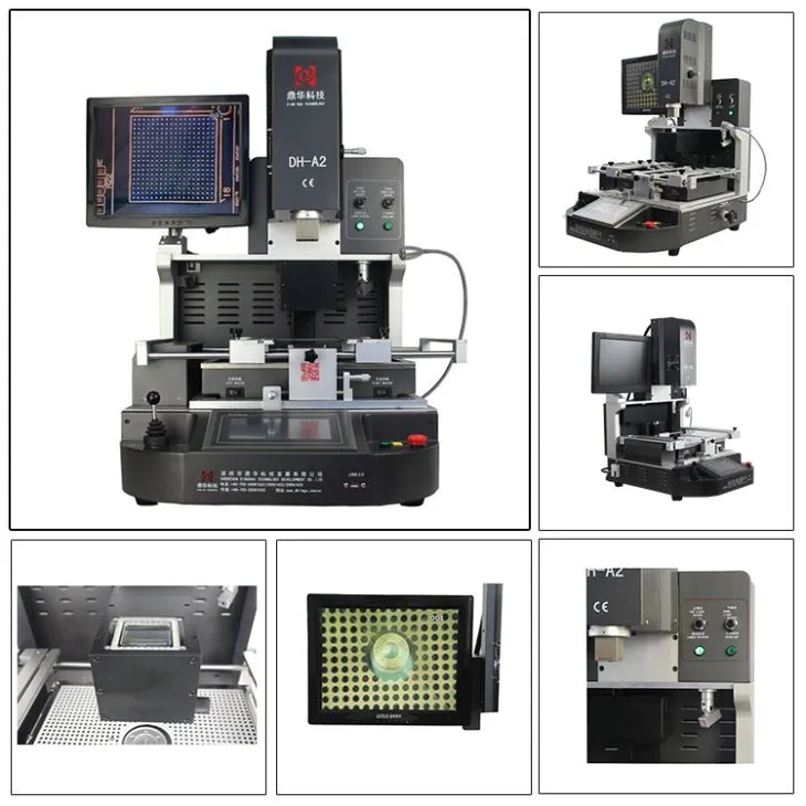

BGA Reballing Machine Price
Widely used in the Chip Level Repair in laptop, PS3,PS4,XBOX360 and Moblie Phone
Rework BGA,CCGA, QFN, CSP, LGA, Micro SMD,LED etc.
Automatic Romoving,Mounting and Soldering.
HD Optical Alignment system for precisely mounting BGA and Components.
Description
BGA Reballing Machine Price


1. Product Features of BGA Reballing Machine Price

• Automatic removing, mounting and soldering. Desoldering, mounting and soldering automatically.
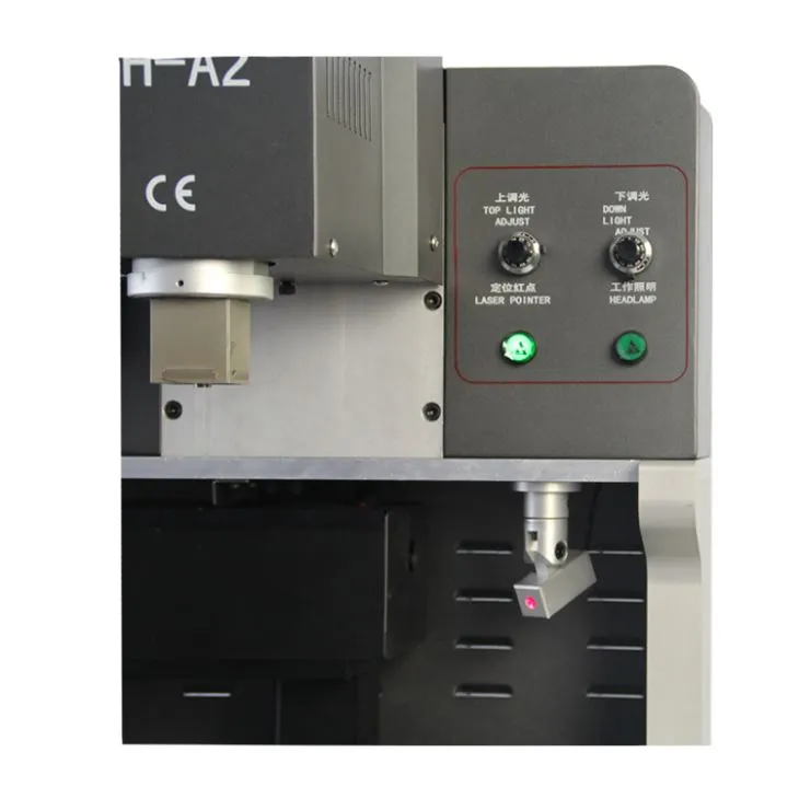
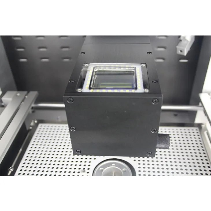
•CCD Camera ensure precise alignment of every soldering joint,
•Three independent heating zones ensure precise temperature control.
•Hot air multi-hole round center support is especially useful for big-size PCB and BGA located in the center of
PCB. Avoid cold soldering and IC-drop situation.
•Temperature profile of bottom hot air heater can reach as high as 300°C, critical for big size motherboard.
Meanwhile, upper heater could be set as synchronized or independent work.
2.Specification of BGA Reballing Machine Price

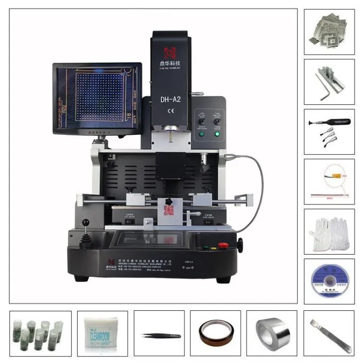
3.Details of BGA Reballing Machine Price


4.Why Choose Our BGA Reballing Machine Price?


5.Certificate of BGA Reballing Machine Price
To offer quality products, SHENZHEN DINGHUA TECHNOLOGY DEVELOPMENT CO.,LTD was the first to
pass UL, E-MARK, CCC, FCC, CE ROHS certificates. Meanwhile, to improve and perfect the quality system,
Dinghua has passed ISO, GMP, FCCA, C-TPAT on-site audit certification.

6.Packing & Shipment of BGA Reballing Machine Price

7. Related Knowledge About Motherboard Repairing
1. Board Checking Methods
1) Observation Method
Check whether there are signs of burning, scorching, foaming, PCB damage, socket rust, or water traces.
2) Multimeter Measurement Method
Check whether the resistance between +5V and GND is too small (below 50 ohms).
3) Power-On Inspection
For faulty boards, the voltage can be slightly adjusted to 0.5–1V. After powering on, use your hand to touch ICs on the board to identify abnormal heating and locate problematic chips.
4) Logic Probe Inspection
Use a logic pen to check whether the signal levels at the IC input, output, and control pins are normal (strong or weak).
5) Identifying Major Functional Areas
Most motherboards have clear functional areas, such as the control area (CPU), clock area (crystal oscillator and frequency division), background display area, motion control area (characters, objects), and sound synthesis area. Understanding these areas is very important for in-depth motherboard repair.
2. Troubleshooting Methods
1) For suspected ICs, follow the circuit diagram and first check whether input and output signals (waveforms) are present.
If there is no input signal, check the IC control signals such as the clock. If input and control signals are normal, the IC is likely faulty. If no control signal is present, trace back to the previous stage until the damaged IC is found.
2) Do not remove the IC immediately. Use another IC of the same model or with the same program content for replacement and power on the board to confirm whether the IC is faulty.
3) Use the cutting and jumper wire method to locate short circuits. If signal lines, ground lines, or +5V lines of multiple ICs are shorted, cut the trace and measure again to determine whether the fault lies in the IC or on the PCB surface. You can also borrow signals from other ICs and connect them to the faulty IC to observe waveform or display changes.
4) Comparison Method
Use a known-good motherboard of the same model to measure and compare IC pin waveforms and pin numbers to determine whether an IC is damaged.
5) Test ICs using ICTEST software with a universal programmer (ALL-03/07, EXPRO-80/100, etc.).
3. IC Removal Methods
1) Cutting Method
Does not damage the PCB, but the IC cannot be reused.
2) Drag Solder Method
Apply solder to both sides of the IC pins and drag it back and forth with a high-temperature soldering iron to remove the IC. This may damage the PCB but protects the IC for testing.
3) Heating Method
Heat the board using alcohol lamps, gas stoves, or electric heaters. Once the solder melts, remove the IC. This method is difficult to control.
4) Solder Pot Method
Use a specially made solder pot heated on an electric furnace. After the solder melts, immerse the IC area into the solder pot to remove the IC without damaging the PCB. However, the equipment is difficult to manufacture.
5) Hot Air Gun Method
Use a professional hot air gun to heat the IC area until the solder melts, then remove the IC. The air gun should be moved continuously to avoid damaging the PCB. This equipment is relatively expensive (generally around 2,000 RMB).
4. Main Causes of Motherboard Failure
1) Human-Caused Faults
Plugging or removing I/O cards while powered on, or using excessive force during installation, which damages interfaces or chips.
2) Poor Operating Environment
Static electricity can easily damage chips on the motherboard, especially CMOS chips. Power supply failures or voltage spikes can damage chips near the power connector. Excessive dust can also cause signal short circuits.
3) Device Quality Issues
Damage caused by poor-quality chips or components. Dust is one of the biggest enemies of the motherboard.
5. Operating Instructions
Pay close attention to dust prevention. Use a soft brush to gently clean dust from the motherboard. Some cards and chips use pin-type connections, which may suffer from poor contact due to oxidation. Use an eraser to remove surface oxidation and reinsert the components.
Cleaning agents such as trichloroethane (volatile solvent) can also be used for motherboard cleaning.
In case of sudden power failure, immediately shut down the computer to prevent damage to the motherboard and power supply. Improper BIOS settings (such as overclocking) can be cleared using jumpers. If the BIOS is corrupted (for example, by a virus), it must be reprogrammed. Since BIOS faults cannot be measured directly with instruments, reflashing the BIOS is recommended to eliminate possible software-related issues.
System failures can be caused by the motherboard itself or by expansion cards on the I/O bus. The plug-and-play troubleshooting method involves removing expansion cards one by one and observing system behavior. If the system works normally after removing a certain card, the fault lies in that card or its corresponding I/O slot.
If the system still does not start normally after all cards are removed, the fault is likely on the motherboard. The replacement method involves swapping identical boards or chips and observing changes in fault behavior. This method is commonly used for easily replaceable components such as memory modules.


