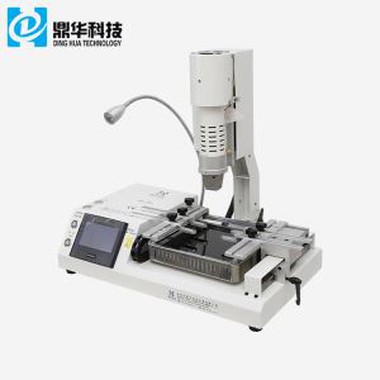
Hot Air Touch Screen BGA Soldering Station
Hot air touch screen BGA soldering station We are a manufacturer cooperating with some international companies, such as, Foxconn, Lenovo and Huawei etc. more than 8 years in the field about BGA/SMT rework station. Bga rework stations are selling well all over the world, and we have agents in...
Description
We are a manufacturer that has been cooperating with international companies, such as Foxconn, Lenovo, and Huawei, for over 8 years in the field of BGA/SMT rework stations. Our BGA rework stations are sold worldwide, and we have agents in countries such as Iran, the USA, Mexico, India, and Vietnam. We hope you can join us too. Your satisfaction is always our pursuit.
Features
- Widely used for reworking CPU and GPU chips on laptops, PS3, PS4, XBOX360, etc.
- Soldering, desoldering, removing, and mounting BGA chips through manual operation.
- Equipped with both top and bottom hot air heaters, and a bottom infrared heating plate.
- User-friendly touch screen interface for easy operation.
- Supports reworking of BGA, CCGA, QFN, SMD components, etc.
- Precise temperature control with an accuracy of ±2°C.
- Superior safety functions, including emergency protection.
The product parameter
|
Total Power |
4800W |
|
Top heater |
800W |
|
Bottom heater |
2nd 1200W, 3rd IR heater 2700W |
|
Power |
AC220V±10% 50Hz |
|
Lighting |
Taiwan led working light, any angle adjusted. |
|
Operation mode |
Drawer style HD touch screen,intelligent conversational interface, digital system setting |
|
Storage |
50000 groups |
|
Top heater movement |
Right/left, frontward/backward, rotate freely. |
|
Positioning |
Intelligent positioning, PCB can be adjusted in X, Y direction with "5 points support" + V-groov PCB bracket + universal fixtures. |
|
Temperature control |
K sensor, close loop |
|
Temp accuracy |
±2℃ |
|
PCB size |
Max 390×400 mm Min 22×22 mm |
|
BGA chip |
2x2 mm - 80x80 mm |
|
Minimum chip spacing |
0.15mm |
|
External temper sensor |
1pc |
|
Dimensions |
610*620*560mm |
|
Net weight |
40KG |
|
|
|
|
The product feature

Machine's emergency button, any urgent condition, it can be pressed, then BGA rework
machine immediately stop working, and cross-flow fan start to cool for PCB/chip and in-
frared preheating area.

Tempe sensor can monitor the real-time temperature on chip, USB 2.0 for software uploading
or downloading the screenshot etc.

Air switch, which will stop when currency is not normal(more or less), such as, leakage
of electricity, short circuit, the power voltage exceeds the normal scope(+/- 10%).
"GND" for connecting the ground wire to provide safer technology using machine.

How Does the BGA Soldering Station Work?
The BGA soldering station features a tidy and simple operation interface, with one temperature sensor port, a USB 2.0 port, a light switch, and an emergency button. The industrial computer, equipped with a 7-inch touch screen, can store up to 5,000 profiles, allowing you to save successful profiles for future reference.
Product Qualification of the Hot Air Touch Screen BGA Soldering Station

The image above shows a simulated automobile transportation machine. All of our machines undergo a rigorous testing process: they run continuously for 3 days, then are subjected to at least 24 hours of vibration testing. After this, they run for an additional 24 hours to identify any potential issues and prevent future problems for our customers. To date, we are the only company in China that conducts such thorough testing in this industry.
FAQ
Q: What is a PCB?
A: A PCB (Printed Circuit Board) is made from layers of fiberglass and copper that are glued together.
Q: Can I use 110V for this machine?
A: Yes, the machine can operate on 110V, but please notify us in advance, as some components may need to be adjusted.
Q: Can I use a desoldered chip to solder it onto a PCB again?
A: Yes, as long as the base point remains intact, the chip can be reused after being re-balled.
Q: How can I identify which chip has a problem?
A: Usually, you would need an X-ray machine to diagnose the issue.
A Few Tips on Repairing: Conductor Repair and Welding Method
Before using any welding equipment, certain precautions should be taken. Ensure that the equipment's electrodes are cleaned, aligned, and set for the appropriate board thickness.
Test samples with similar circuit widths, spacing, thickness, surface finish, and contour should be used. Observe and test the weld quality, alignment, discoloration, fusion, and the appearance of the base material in the weld area. Adjust the weld equipment settings and repeat until an acceptable result is achieved.
The alignment of the welded ribbon to the circuit pattern should be within 0.050 mm (0.002"). The bond strength of the weld should exceed that of the circuit/base material.
Procedure
- Clean the area.
- Select a section of Kovar ribbon that matches the width of the conductor pattern being repaired (± 0.050 mm, or 0.002").
- Cut the ribbon approximately 3.0 mm (0.120") longer than the section being repaired.
- Clean the ribbon conductor and the base material around the repair area.
- Place and center the ribbon over the section to be repaired, leaving equal lengths on each side, parallel to the circuit pattern.
- Position the PC board under the weld electrodes so that the electrodes press on the repair area.
- Hold the ribbon in place with precision tweezers until the weld is completed. Weld in place using settings based on the accepted test samples.
- Clean the area.
- Carefully inspect the joint for weld quality and alignment.
- If necessary, apply a small amount of flux and tin the entire area with solder.
- Clean the area again.
If required, coat the repaired area with epoxy.