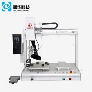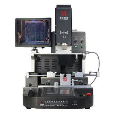
Laser Position SMD Rework Station
1. Model DH-A2 . 2. Directly from factory. 3. Laser positioning. 4. automatic and optical . 5. Desoldering ,soldering and reballing
Description
Laser Position SMD rework station


1.Application Of Laser Position SMD rework station
Can repair motherboard of computer, smart phone, laptop, MacBook logic board, digital camera ,air conditioner, TV and other electronic equipments from medical industry, communication industry, automobile industry, etc.
Solder, reball, desoldering different kind of chips: BGA,PGA,POP,BQFP,QFN,SOT223,PLCC,TQFP,TDFN,TSOP, PBGA,CPGA,LED chip.
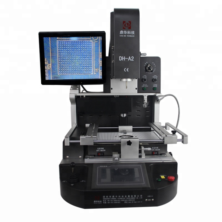
2.Product Features of Laser Position SMD rework station

* High level of automation with high successful rate
* 3 indepentdent heater enable strict temperature control
* 600 million pix Panasonic original CCD camera ensures precise alignment of every soldering joints.
* User-friendly. Can learn to use in 30 minutes.
3.Specification of Laser Position SMD rework station

4.Details of Laser Position SMD rework station


5.Why Choose Our Laser Position SMD rework station?


6.Certificate of Laser Position SMD rework station
To offer quality products, SHENZHEN DINGHUA TECHNOLOGY DEVELOPMENT CO.,LTD was the first to pass UL, E-MARK, CCC, FCC, CE ROHS certificates. Meanwhile, to improve and perfect the quality system, Dinghua has passed ISO, GMP, FCCA, C-TPAT on-site audit certification.

7.Packing & Shipment of Optical Alignment BGA Reballing Station

8.Shipment for Laser Position SMD rework station
We will ship the machine via DHL/TNT/FEDEX. If you want other shipping term, please tell us. We will support you.
9. Terms of Payment
Bank transfer, Western Union, Credit Card.
Please tell us if you need other support.
10. Operation guide for Laser Position SMD rework station
11. Related knowledge
Diagnostic Card Code After Powering On the Motherboard
After the motherboard is powered on, if the diagnostic card code does not change and remains at 00 or FF, it usually indicates that the CPU is not working.
At this point, turn off the power and remove the CPU fan. Carefully touch the CPU with your hand (preferably between your fingers and the CPU, keeping heat sources separated to avoid burns). Slightly press and hold the power button.
If there is still no response and the motherboard does not start, the CPU socket may have discharged. The next step is to determine whether the CPU power supply circuit is faulty.
First, understand the routing of the CPU power supply circuit on the motherboard. Under normal conditions, the CPU power circuit layout is reasonable and located around the CPU area. The CPU uses a 5V power supply. Connect the black probe of the multimeter to ground and the red probe to the 5V interface. Then connect the red probe to the four-pin auxiliary CPU power interface (set the multimeter to continuity/buzzer mode). If the multimeter beeps, the circuit is normal.
Next, place the black probe on a pin of the CPU auxiliary power interface, and slide the red probe across the pins of the U-chip next to the CPU. If a short beep occurs, stop immediately. The corresponding pin is the CPU 5V power supply pin (this U-chip is the power management chip).
Then check the two pairs of MOSFETs next to the CPU. MOSFETs should not show continuity between all three pins. If all three pins are conducting with each other, the MOSFET is damaged and must be replaced.
Finally, measure the capacitors and resistors around the CPU socket. If power is present, the CPU power supply circuit is generally normal. Common failure points in the CPU circuit include MOSFETs, the power management chip, and capacitors.
Overall Motherboard Testing Procedure
Insert the diagnostic card and install components step by step: first the CPU, then memory, and finally the discrete graphics card. The diagnostic code usually starts at 00 or FF, and then progresses to codes such as 01, C1, 24, 25, 26, etc.